
Head Pulley Support
Supports the drive or discharge pulley and its conveyor interfaces.
Structural support assemblies for conveyor pulleys, intermediate sections and take-up arrangements, configured according to belt width, pulley layout, conveyor duty and installation geometry.
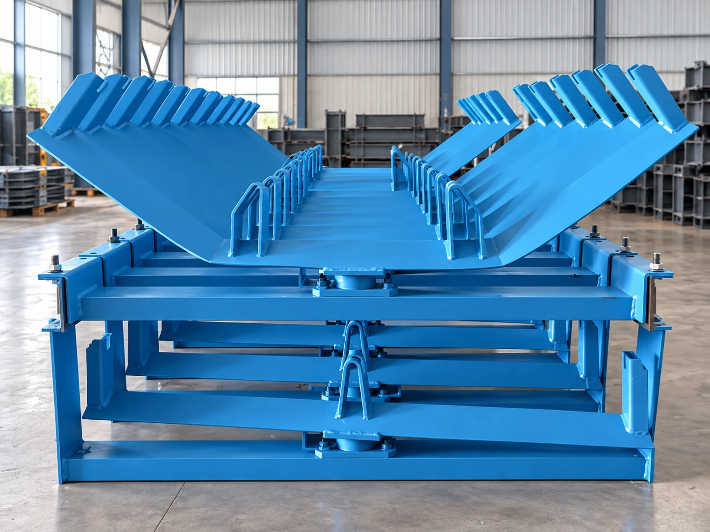
Junxin manufactures conveyor support frames for pulleys, intermediate conveyor sections and take-up equipment. The frame arrangement is developed from the pulley position, belt width, conveyor tension, pulley wrap, operating duty and overall conveyor layout.
Available arrangements include head-pulley supports, tail or bend-pulley supports, intermediate drive supports, intermediate frames and legs, and take-up support structures. We manufacture the main dimensions, bracing, mounting points, connection holes and foundation interfaces to the approved general arrangement and fabrication drawing.
DTII(A) dimensional ranges are identified separately from the other listed conveyor series.
Support geometry follows the component position and the interfaces shown on the confirmed conveyor arrangement.
Supports the drive or discharge pulley and its conveyor interfaces.
Configured for tail, bend or take-up-side pulley positions.
Carries a drive pulley installed within the conveyor route.
Forms the structural support for conveyor sections between pulley stations.
Supports screw, vertical or trolley take-up arrangements.
For DTII(A) arrangements, the standard intermediate-frame section is 6000 mm. Non-standard sections from 3000 to 6000 mm can be configured where the conveyor route or installation boundary requires them.
Leg position, bracing and section spacing follow the conveyor arrangement and approved connection details.
The final support structure is defined from the take-up travel, pulley arrangement and available installation geometry.
Compact adjustment at the pulley support.
Structure configured around the vertical counterweight geometry.
Support interfaces arranged for the trolley and counterweight path.
Send the available conveyor layout and interface data. Existing general-arrangement or foundation drawings can be reviewed before quotation.
Send Your DrawingExisting Junxin support-frame fabrication and finished-stock views.
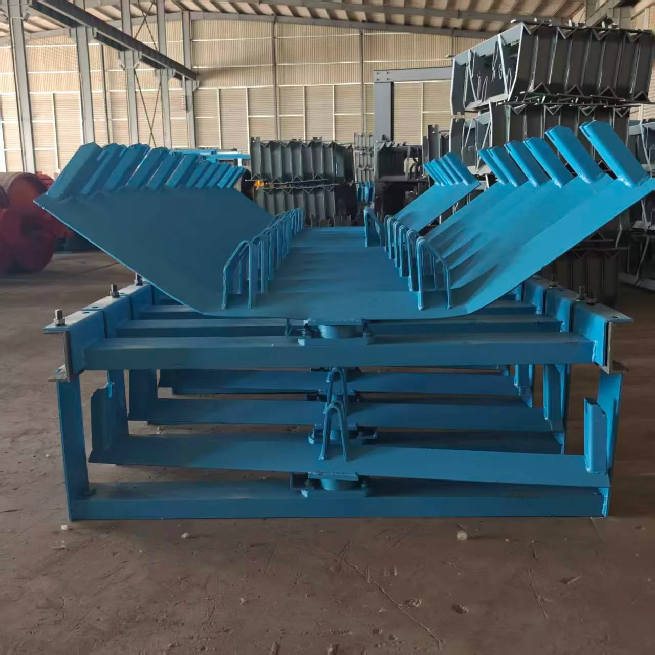
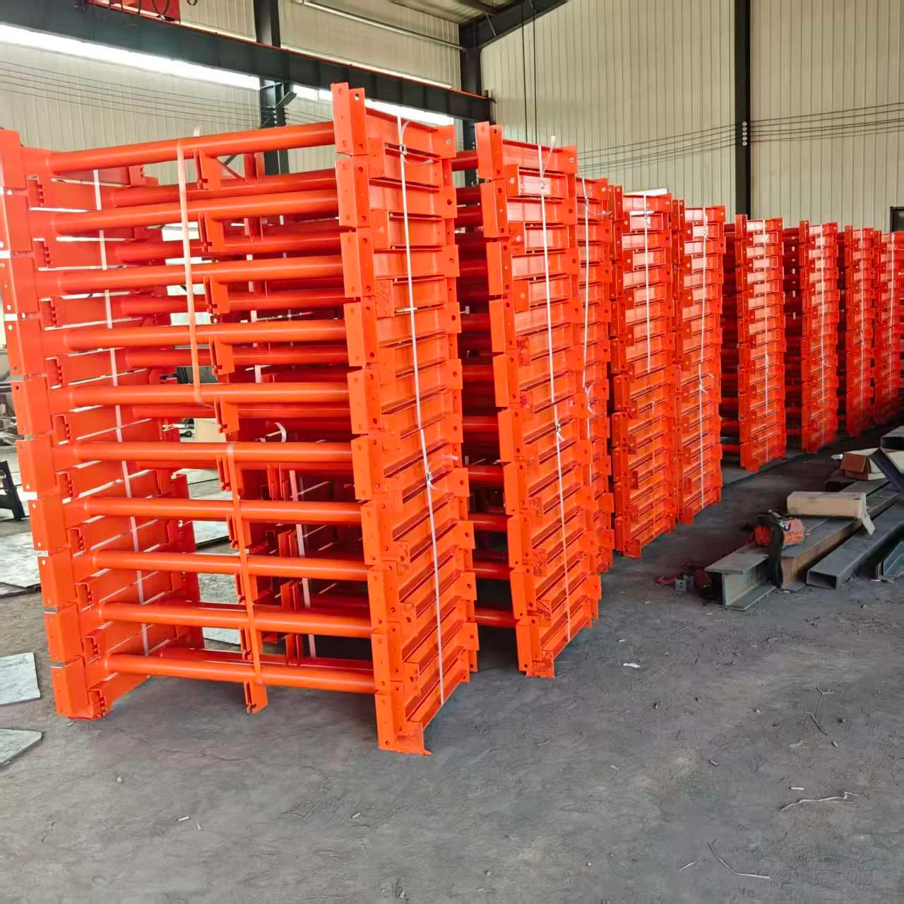
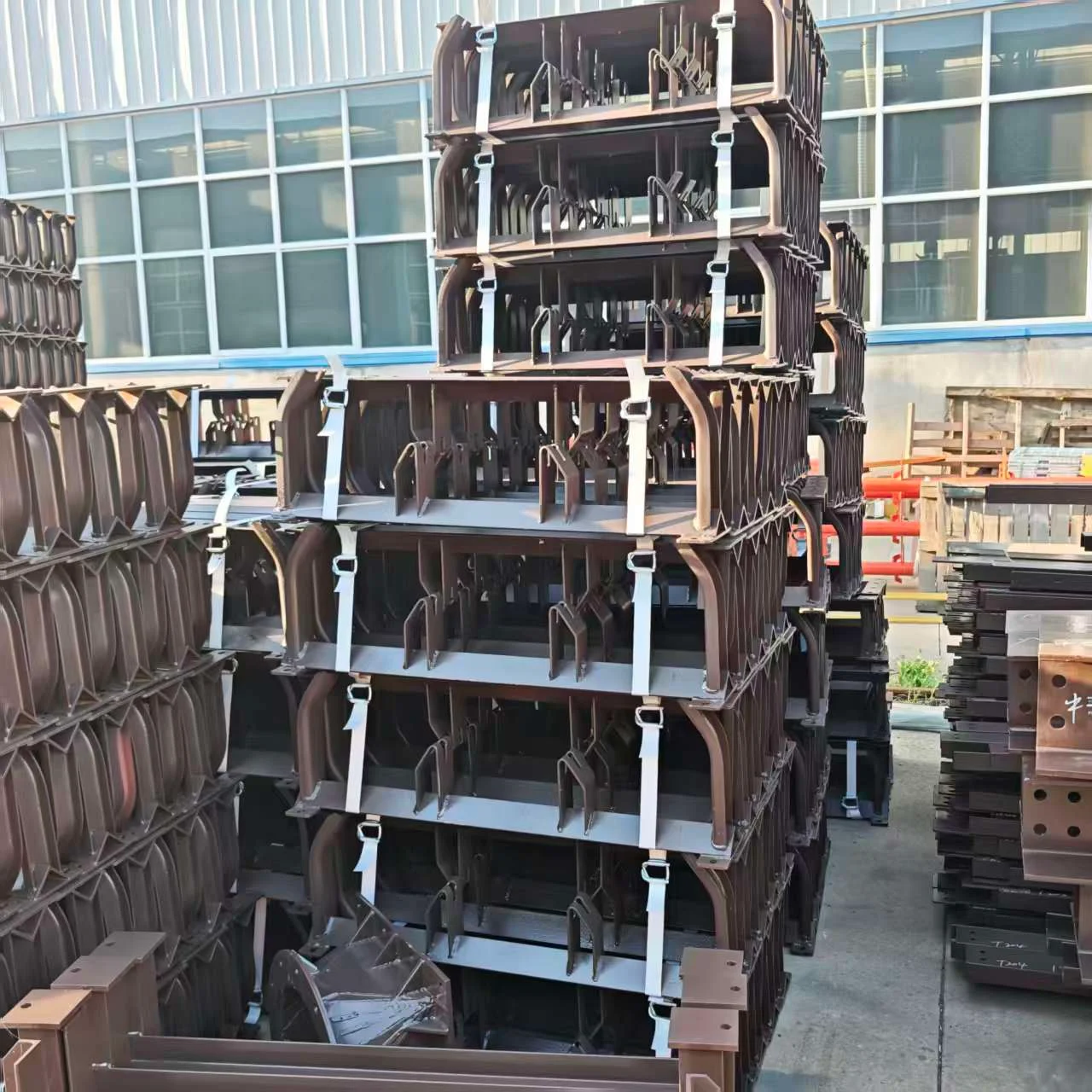
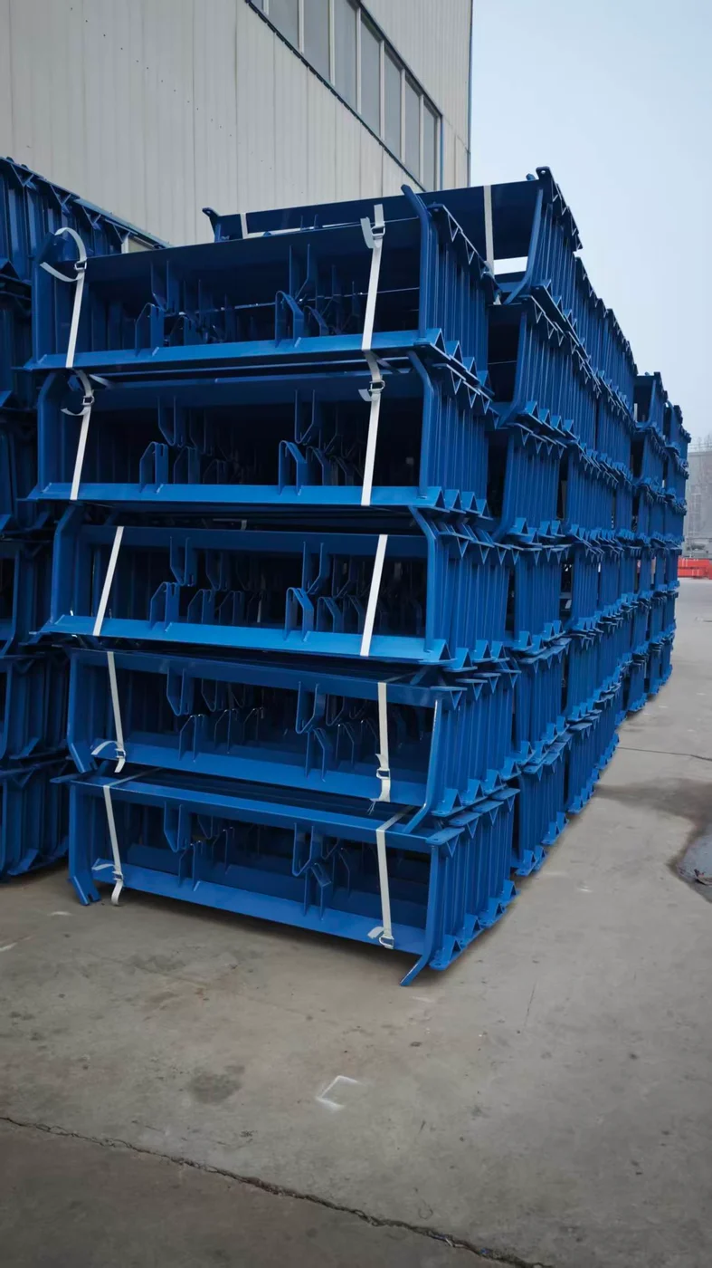
Junxin checks structural dimensions, pulley mounting interfaces, connection-hole positions, frame alignment and foundation or support connections against the approved fabrication drawing.
Provide the conveyor series, belt width, pulley diameter and position, drive or bend arrangement, belt tension or duty, support height, foundation interface and an existing layout drawing where available.
Yes. Existing general-arrangement and fabrication drawings can be reviewed, with critical dimensions and interfaces confirmed before production.
Yes. Head drive, tail bend, head bend, intermediate drive and suspended or intermediate-support arrangements can be configured according to the conveyor layout.
Yes. For DTII(A) arrangements, 6000 mm is the standard section length and non-standard sections from 3000 to 6000 mm can be configured. Other conveyor series are reviewed against their project drawings.
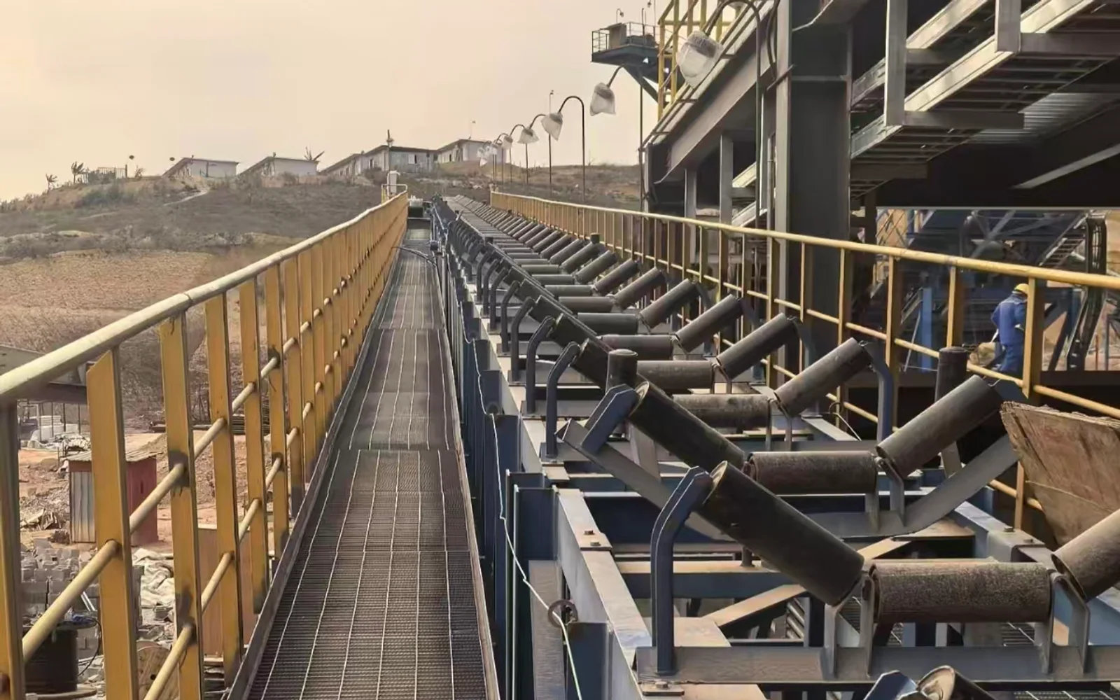
Junxin DTII belt conveyor systems configured for the required material, capacity, route, belt width, drive and take-up arrangement.
View product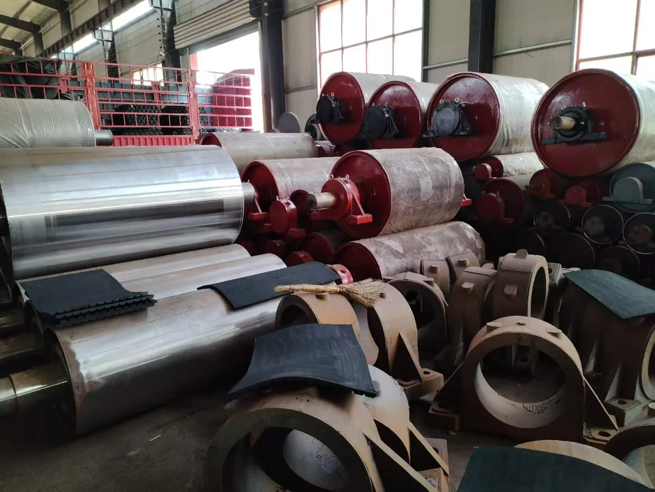
DTII(A) drive pulleys manufactured to the required torque, belt load, shaft, bearing and installation interfaces.
View product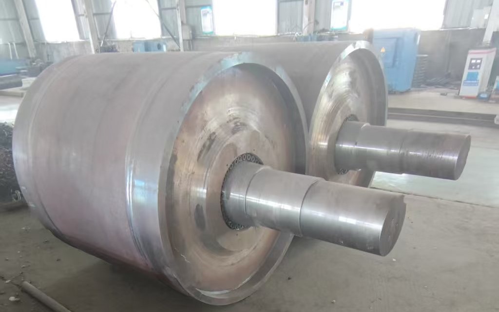
DTII(A) bend pulleys manufactured for head, tail, take-up and other belt-redirecting positions.
View product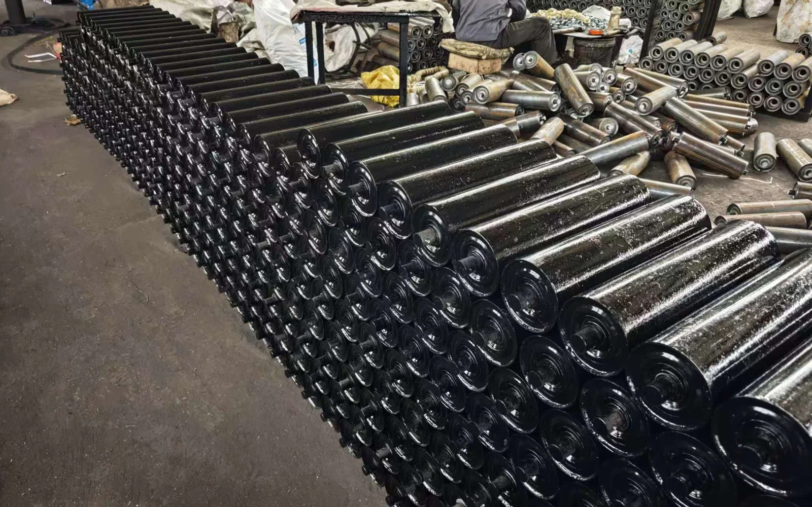
DTII(A) conveyor idlers manufactured in multiple diameters, lengths and bearing arrangements for new and replacement conveyors.
View productShare the conveyor arrangement, pulley interface and foundation data available for review. Existing drawings provide the clearest basis for a replacement or project-specific frame.